EzyCad 2D Sketching Guide
This guide covers all 2D sketching tools and operations in EzyCad. For the main usage guide (workflow, 3D modeling, file operations, etc.), see usage.md.
Table of Contents
Sketching (2D)
Basic Tools
Sketch Operations
 Operational axis - Define a reference axis, then use the Mirror and Revolve controls (in the Options panel) to mirror selected sketch edges or revolve edges/faces into 3D solids.
See Sketch origin — every sketch includes one permanent reference point. Edge and face colors (including selection highlight and transparency) are in Settings -> Sketch -> Appearance (see usage-settings.md).
While a sketch tool is active, document shapes can stay visible as context: Options -> Sketch options -> Faint shapes (all sketch tools; default on) toggles this. Style and Shape Faint Strength are in Settings -> Sketch -> Appearance: Ghost (default), Wire, or Off (hide); strength (5%–85%, default 14%) sets how solid they look. Faint shapes are display-only (no yellow hover/selection highlight). Shape List -> Hide all still hides every shape. Leaving sketch mode restores each shape’s normal shaded/wire look.
Sketch origin
Every sketch has exactly one Origin — a fixed reference point on the sketch plane, shown as a + inside a circle on the active sketch only (a permanent node, not placed with a tool) whenever that sketch is visible in sketch mode (and in tools such as polar duplicate that snap to sketch nodes). User-placed Add node points use a red + without a circle on every visible sketch. Color is set in Settings -> Sketch -> Origin marker color.
When created |
Added automatically when the sketch is created; you do not place it with a tool. |
Location (reference plane) |
Sketch plane coordinates (0, 0) — the plane’s built-in reference origin (XY, XZ, YZ, or offset reference planes). |
Location (from face) |
Center of the bounding box of the face boundary wire when you use Create sketch from planar face. |
Sketch List |
Listed as Origin under Nodes when you expand a sketch row (see Sketch List). |
Snapping |
Acts like any other sketch vertex when the marker is shown: axis guides, vertex lock, and distance snap apply. Origins from other visible sketches (with marker shown) are also snap targets on the current plane. When Show origin marker is off, the Origin is not a snap target. |
Cannot delete |
The Origin cannot be selected or deleted. Hide it with Show origin marker in Sketch properties instead. |
Marker size |
Settings -> Sketch -> Permanent node annotation size ( |
Marker color |
Settings -> Sketch -> Origin marker color ( |
Sketch properties |
Sketch List -> [P] — Show origin marker, Position sliders (range follows the current view) with Set for typed values. |
Tips
Use the Origin as a stable anchor when you need a known center (especially on face-derived sketches).
If the + is hard to see, increase Permanent node annotation size in Settings.
Open Sketch properties ([P] on the sketch row) to drag X / Y sliders (view-relative range) or use Set beside each slider, type a value, and press Enter.
While an operational axis is active in mirror/revolve phase, + markers (including Origin) are temporarily hidden so edge and face selection stays clear; they return when you Clear axis or leave that mode.
Sketch snapping
While you draw or place points in sketch mode, EzyCad helps you align to existing geometry. Snap guide mode is listed first in the Options panel; Snap dist and All co-axial nodes follow (and are hidden when mode is None). Snap guide color, Snap guide line width (desktop only), and the same mode/co-axial toggles are in Settings -> Sketch (see usage-settings.md).
Snap distance |
Larger Snap dist values let snaps engage from farther away (screen pixels, converted to the sketch plane at the cursor). Hidden when Snap guide mode is None. |
Snap guides |
Snap guide mode: Traditional (local markers at guide intersections), Fullscreen (view-spanning axis lines), Both, or None (no snap-to-node and no guides). Snap guide color (node) is used when both X and Y align to the same vertex; Snap guide color (axis) when only one axis aligns. A separate checkbox All co-axial nodes (in the sketch Options panel and in Settings; hidden when mode is None) enables global mode: when on, full horizontal and vertical guide lines + markers are shown for all nodes in the current sketch and all other visible sketches (the complete set of co-axial alignments). When off (default), only the closest node per active axis is annotated (classic closest-relative behavior). |
Axis alignment |
Near a snap target, the pick can align to that point’s X or Y on the sketch plane; guides show which axis is active. When both axes align to the same point, the cursor locks to that vertex. |
Sketch origin |
Each sketch’s built-in Origin (see Sketch origin) is a snap target when its marker is shown. |
Mid-point snap (Add node) |
A click near a straight edge (not at its ends) snaps onto the segment and splits it at commit time (see Add node tool). Separate from vertex lock. |
Automatic splitting on edge intersections |
When you add a new straight (linear) edge using the Line Edge tool or Multi-Line Edge tool, if it crosses or touches the interior of any existing straight edge, the existing edge is automatically split at the intersection point. The new edge is also subdivided into atomic segments where needed. The same splitting occurs when an endpoint of the new edge snaps to the midpoint of an existing edge. When you add an arc segment, existing straight and arc edges are split at interior crossings, and the new arc is subdivided at intersection points on its interior. This produces correct T-junctions, crossings, and cleanly divided faces from a single sketch. |
Other visible sketches |
Nodes from other visible sketches are projected onto the current sketch plane and act as snap targets (same distance rules). Each visible sketch contributes its Origin when that sketch’s marker is shown, plus any user-placed nodes. Useful for multi-sketch layouts and tools such as polar duplicate that pick sketch points. |
Operational axis mode |
While an operational axis is defined and Operational axis mode is active (mirror/revolve phase), sketch snap and permanent + node markers are suppressed so edge and face selection stays clear. Normal snapping applies again after Clear axis or when you leave the tool. Axis placement (before the axis exists) still uses snap. |
Angle constraint: When a line or add-node rubber band has an active angle constraint, vertex and axis snap may be disabled or relaxed so the typed angle stays exact (see each tool’s section).
Tips:
For precise corners, approach a vertex until both horizontal and vertical guides appear, then click.
Edge midpoints (for straight edges) are optional snap targets. By default (see Settings > Sketch), no midpoint nodes are created for new linear edges from the Line or Multi-Line tools. When enabled, they are snap targets but do not show + markers and are not listed under Nodes in the Sketch List. That list shows the sketch Origin plus user-placed Add node points only — not every internal topology vertex or automatic edge midpoint.
Adding a new straight edge that intersects existing straight edges (or snaps to their midpoints) automatically splits the intersected edges. This is the main way to divide a closed shape (rectangle, square, slot, or freehand closed profile) into multiple separate faces for individual extrusion or other operations. No manual “split” command is needed. The resulting faces remain valid even if you add the splitting edge before or after the outer shape.
Hotkeys
Common keyboard shortcuts (hotkeys) while working in 2D sketch mode or with sketch tools. Tool-specific shortcuts are also listed in each tool section later in this guide.
Common sketch hotkeys
Hotkey |
Action |
|---|---|
Tab |
Open precise distance / length / radius / size input dialog (most creation tools) |
Shift+Tab |
Open angle (degrees) input dialog for constrained line / multi-line / add-node placement |
Esc |
Cancel the current tool, step, or rubber-band preview |
Enter |
Confirm current numeric input or finalize the step |
D |
Activate the Dimension tool |
Shift+D / Delete / Backspace |
Delete the selected sketch element(s) or dimension |
Right-click |
In multi-line / sequences: complete current item and continue, or finish the whole operation |
Notes:
Tab / Shift+Tab work even when focus is in the 3D view (they are routed to the active sketch tool for precise entry).
When an angle constraint is active, node snapping is typically relaxed or disabled to preserve the exact angle.
Global hotkeys (mode switches like G Move, undo, view navigation, selection filters) are in the main Hotkeys section.
Move / rotate / polar axis constraints (when those options are active)
Hotkey |
Action |
|---|---|
X |
Toggle / cycle X axis constraint (move) or rotation axis (rotate / polar) |
Y |
Toggle / cycle Y |
Z |
Toggle / cycle Z |
See the individual tool sections (and usage.md#hotkeys) for full context and additional view / general hotkeys.
Line Edge Creation Tools

EzyCad provides tools for creating individual line edges in sketch mode, allowing you to build complex geometries one edge at a time.
Single Line Edge Tool
The single line edge tool allows you to create straight line segments between two points.
Features:
Two-point creation |
Click to set the start point, then click to set the end point |
Real-time preview |
See the line shape while moving the mouse |
Precise length control |
Use the distance input dialog (Tab key) for exact line lengths |
Angle constraint |
Use the angle input dialog (Shift+Tab) to constrain the line to a specific angle |
Snap support |
Automatically snaps to existing nodes and geometry (disabled when angle constraint is active) |
Dimension annotations |
Optional length dimensions can be displayed |
Tool Options |
Add midpoint nodes and Place from center checkboxes (see Line edge Options below); each has a ? help button |
Line edge Options
While the Line Edge tool is active, the Options panel (under the Options heading, below Sketch options and Shortcuts) shows two tool-specific checkboxes. Each row has a small ? button on the right: hover for a short summary, click to open the matching section on Read the Docs.
Line edge option: Add midpoint nodes
When checked, each new straight edge created with this tool (and with Add multi-line edge) gets an automatic midpoint node at the center of the segment. That node is a snap target but does not show a + marker and is not listed under Nodes in the Sketch List.
Default is off (no midpoint nodes on new edges).
The same preference is available globally and persistently in Settings -> Sketch -> Add midpoints to new linear edges (saved as
gui.add_mid_pt_edges). The Options checkbox mirrors that setting for the current session while you use line tools and the Arc Segment tool.Affects future edges from the Line, Multi-line, and Arc Segment tools.
Midpoint snapping on intersection splits (when a new edge crosses an existing one) is separate topology behavior; see Automatic splitting on edge intersections.
Line edge option: Place from center
When checked, the first click sets the midpoint of the new edge (not an endpoint). The second click sets the direction; the distance from the center to that click is half the edge length, so the finished segment is symmetric about the first point.
Tab (distance input) uses the full edge length, not half. Example: center at the origin, direction along +X, Tab →
10produces an edge from (-5, 0) to (5, 0).Shift+Tab (angle) works as usual after the center is placed; combine with Tab for a fixed length and angle.
Default is off (classic two-endpoint placement: first click = start, second click = end).
This option applies only to Add line edge, not Multi-line edge.
How to use:
- Select the Line Edge tool from the toolbar
Optionally enable Add midpoint nodes or Place from center in the Options panel (see Line edge Options)
Click to set the start point of the line (or the center when Place from center is on)
Move the mouse to see a preview of the line
Click to set the end point (or direction when placing from center), or use input dialogs for precise control:
Press Tab to enter an exact length value (full edge length when Place from center is on)
Press Shift+Tab to enter an exact angle value (in degrees)
When using both: apply angle (Shift+Tab) first, then distance (Tab).
The line edge will be created and added to your sketch
Shortcuts:
Tab |
Open distance input dialog for precise length control |
Shift+Tab |
Open angle input dialog to constrain the line to a specific angle (after first point is set) |
Escape |
Cancel the current line creation |
Enter |
Finalize the line (if using distance or angle input) |
Right-click |
Complete the current line and start a new one |
Angle Constraint:
After setting the first point, press Shift+Tab to open the angle input dialog
Enter the desired angle in degrees (0 deg = horizontal right, 90 deg = vertical up, counterclockwise)
Once the angle is entered, the line segment is constrained to that angle
You can still move the mouse to adjust the length while maintaining the angle
The distance input (Tab) can still be used in combination with the angle constraint
Order when using both: When requiring both an angle and a distance constraint, apply the angle constraint first (Shift+Tab), then the distance constraint (Tab).
Note: When an angle constraint is active, snapping to nodes is disabled to maintain the angle precision
Tips:
Use the snap feature to create lines that connect precisely to existing geometry
Lines can be used as construction geometry or as part of your final design
The line tool works in any sketch plane
Multiple line edges can be created in sequence by right-clicking after each line
New straight edges automatically split existing straight edges at interior intersection points (or when snapping to an existing midpoint, if midpoints were created). This is how you divide a closed profile into multiple faces (for separate extrusions, etc.) — just draw the crossing or connecting line; no extra “split” step is required. The same logic applies to multi-line sequences. Midpoint creation for new edges is controlled by Add midpoint nodes in the Line Edge Options panel or Settings > Sketch > Add midpoints to new linear edges (default off).
Place from center is useful for symmetric segments (e.g. a divider through the middle of a rectangle) without measuring half-lengths manually.
Multi-Line Edge Tool

The multi-line edge tool allows you to create multiple connected line segments in a single operation, making it efficient for drawing continuous paths, polylines, or complex connected geometries.
Features:
Continuous edge creation |
Click multiple points to create a chain of connected line segments |
Real-time preview |
See each edge shape while moving the mouse before clicking |
Precise length control |
Use the distance input dialog (Tab key) for exact edge lengths |
Angle constraint |
Use the angle input dialog (Shift+Tab) to constrain the current edge to an angle (in degrees) |
Snap support |
Automatically snaps to existing nodes and geometry |
Distance annotations |
Real-time distance display for the current edge being drawn |
Flexible finalization |
Continue adding edges until you right-click to finalize the entire sequence |
How to use:
- Select the Multi-line Edge tool from the toolbar
Click to set the first point (start of the first edge)
Move the mouse to see a preview of the first edge
Click to set the second point (end of first edge, start of second edge), or use input for precise control:
Press Tab to enter an exact length value
Press Shift+Tab to enter an exact angle (in degrees) for the current edge
When using both angle and distance: apply angle (Shift+Tab) first, then distance (Tab).
Continue clicking to add more connected edges, each new click starts a new edge from the previous edge’s end point
Press Right-click to finalize the entire multi-line sequence and add all edges to your sketch
Shortcuts:
Tab |
Open distance input dialog for precise length control of the current edge |
Shift+Tab |
Open angle input dialog to constrain the current edge to an angle (after first point is set) |
Escape |
Cancel the entire multi-line creation operation |
Enter |
Finalize the current edge length (if using distance input) and continue to the next edge |
Right-click |
Finalize the entire multi-line sequence and complete the operation |
Workflow details:
Each click after the first creates a new edge connected to the previous edge’s end point
After entering a distance with Tab, the tool automatically starts a new edge from the end of the previous one
The distance annotation shows the length of the edge currently being drawn
All edges in the sequence are added to the sketch together when you right-click to finalize
Tips:
Use the snap feature to create multi-line edges that connect precisely to existing geometry
Multi-line edges are ideal for creating continuous paths, outlines, or complex connected shapes
The tool works in any sketch plane
Keep clicking to add more edges - there’s no limit. For example, you can click 3 times to create 2 edges, or 10 times to create 9 edges. All edges remain temporary until you right-click, which adds all of them to your sketch at once
If you make a mistake, press Escape to cancel the entire sequence and start over
The last edge in the sequence will be removed if it hasn’t been finalized (no end point set) when you right-click
Comparison with Single Line Edge Tool:
Single Line Edge: Creates one edge at a time, finalizes automatically after two points
Multi-Line Edge: Creates multiple connected edges in sequence, requires right-click to finalize
Use single line edges when you need individual disconnected segments
Use multi-line edges when you need a continuous chain of connected segments
Circle Creation Tools

EzyCad provides a method for creating circles in sketch mode using the center-radius approach.
Center-Radius Circle Tool
The center-radius circle tool allows you to create circles by defining a center point and a radius point.
Features:
Two-point creation |
Click to set the center, then click to set the radius point |
Real-time preview |
See the circle shape while dragging the radius point |
Precise radius control |
Use the distance input dialog (Tab key) for exact radius values |
Angle constraint |
Use the angle input dialog (Shift+Tab) to constrain the direction from the center to the radius point |
Snap support |
Automatically snaps to existing nodes and geometry (disabled when angle constraint is active) |
How to use:
- Select the Circle tool from the toolbar
Click to set the center point of the circle
Move the mouse to see a preview of the circle
Click to set the radius point, or use input dialogs for precise control:
Press Tab to enter an exact radius value
Press Shift+Tab to enter an exact angle value (in degrees, CCW from +X) to constrain the direction from the center
When using both: apply angle (Shift+Tab) first, then radius (Tab).
The circle will be created and added to your sketch
Shortcuts:
Tab |
Open distance input dialog for precise radius control |
Shift+Tab |
Open angle input dialog to constrain the radius direction from the center (after center point is set) |
Escape |
Cancel the current circle creation |
Enter |
Finalize the circle (if using distance input) |
Angle Constraint:
After setting the center point, press Shift+Tab to open the angle input dialog
Enter the desired angle in degrees (0 deg = horizontal right from center, 90 deg = vertical up, counterclockwise)
Once the angle is entered, the radius point placement is constrained to that direction from the center
You can still move the mouse to adjust the radius (distance from center) while maintaining the direction, or use Tab for an exact radius value
The distance input (Tab) can still be used in combination with the angle constraint
Order when using both: When requiring both an angle and a radius constraint, apply the angle constraint first (Shift+Tab), then the radius constraint (Tab).
Note: When an angle constraint is active, snapping to nodes is disabled to maintain the angle precision
Tips:
Use the snap feature to create circles that are precisely positioned relative to existing geometry
The circle tool works in any sketch plane
Circles can be used as construction geometry or as part of your final design
Constraining the angle when placing the radius point is useful for precise directional placement (e.g. for future snapping operations involving circle nodes)
Three-Point Circle Tool (Planned Feature)
Status: Not yet implemented
The three-point circle tool is planned for future development. This feature would allow creating circles by defining three points that lie on the circle’s circumference.
Planned Features:
Three-point creation |
Click three points that lie on the circle’s circumference |
Automatic center and radius calculation |
The system would compute the center and radius from the three points |
Geometric validation |
Ensure the three points are not collinear |
Note:  The toolbar icon exists but the functionality is not yet implemented.
Circle Creation Workflow
The circle tool follows this workflow:
Activate Tool: Select the circle creation mode
Point Placement: Click to place the center point, then click to place the radius point (use Tab for exact radius or Shift+Tab for angle constraint on the direction from center)
Preview: See real-time preview of the circle as you move the mouse
Finalization: Click to complete the circle creation
Integration: The circle becomes part of the sketch and can be used for further operations
Precise control with Tab / Shift+Tab works the same as for line edges (see Line Edge Creation Tools)
Common Operations with Circles:
Extrusion |
Select the circle face and extrude to create cylindrical shapes |
Boolean Operations |
Use circles in cut, fuse, or common operations |
Pattern Creation |
Use circles as the basis for polar arrays or other patterns |
Dimensioning |
Add radius or diameter dimensions to circles |
Error Handling:
Coincident Points |
The system prevents creation of circles with zero radius |
Invalid Geometry |
Circles that would be too small are rejected |
Snap Integration |
Use existing snap points for precise circle placement |
Arc Segment Creation Tool

The arc segment tool creates a single circular arc edge from three clicks: start, a bulge point on the arc (between start and end), and end.
Features:
Three-point creation |
Click start, then a point on the arc that sets bulge/curvature, then end |
Rubber-band preview |
After the first click, a straight preview line follows the cursor; after the second click, an arc preview follows the cursor until the third click |
Automatic finalization |
The arc is created and added to the sketch after the third click |
Circular arc |
One smooth circular arc through the three defining points |
Intersection splitting |
Splits existing straight and arc edges at interior crossings; the new arc is subdivided where other edges cross its interior |
Optional arc midpoint node |
When Add midpoint nodes is on in the Options panel, a snap node is placed at the arc’s geometric midpoint (see Arc segment Options) |
Snap support |
Snaps to existing nodes and geometry |
Unique points |
All three clicks must be different (cannot be coincident) |
How to use:
- Select the Arc Segment tool from the toolbar
Optionally enable Add midpoint nodes in the Options panel (see Arc segment Options)
Click to set the start point (first click)
Move the mouse — a straight rubber-band line shows from start to the cursor
Click to set a bulge point on the arc (second click — between start and end, not necessarily at the geometric midpoint)
Move the mouse — an arc preview follows the cursor from start through the bulge point toward the end
Click to set the end point (third click)
The arc is created and added to your sketch; faces update if the sketch forms closed regions
Point order:
First click |
Start — where the arc begins |
Second click |
Bulge point — any point on the intended arc between start and end (sets which side of the chord the arc bulges) |
Third click |
End — where the arc ends |
Shortcuts:
Escape |
Cancel the current arc creation (clears all points) |
Note |
The arc is automatically finalized after the third click; no manual finalization is needed |
Arc segment Options
While the Arc Segment tool is active, the Options panel shows the same Add midpoint nodes checkbox used by the Line Edge tool (see Line edge option: Add midpoint nodes).
When on, each new arc gets an automatic midpoint node at the geometric center of the arc curve (parametric half). That node is a snap target only; it does not show a + marker and is not listed under Nodes in the Sketch List.
When off (default), only the three clicked points (start, bulge, end) are stored as nodes.
The setting mirrors Settings -> Sketch -> Add midpoints to new linear edges (
gui.add_mid_pt_edges) for the current session.
Tips:
The three clicks define a unique circular arc; the second click controls bulge direction (which side of the chord the arc curves toward).
Use snap to connect arc endpoints precisely to existing geometry.
Adding an arc across an existing straight edge splits that edge at the crossing; adding a line across an existing arc splits the arc at the crossing.
Arc segments combine with straight edges to form closed shapes (slots, circles, custom profiles).
Known limitations:
Combining a slot with a circle that crosses the slot horizontals can still produce incorrect edge splits or highlight colors in some cases. See Known bugs — slot + circle in the bug tracker.
Technical notes:
Each arc is one graph edge (start and end nodes only); face detection uses arc tangents at endpoints when walking closed loops.
JSON save/load stores arc mid coordinates when no midpoint node is present.
Comparison with Circle Tool:
Circle Tool: Creates a full circle from center and radius point (2 points, two semicircular arc edges)
Arc Segment Tool: Creates one partial arc from three points (start, bulge, end)
Use circles when you need a complete circular shape; use arc segments for partial curves in larger shapes
Rectangle and Square Creation Tools
EzyCad provides three tools for creating rectangular shapes in sketch mode: square, rectangle from two points, and rectangle with center point.
Square Tool

The square tool allows you to create perfect squares by defining a center point and an edge midpoint.
Features:
Two-point creation |
Click to set the center point, then click to set the midpoint of one edge |
Real-time preview |
See the square shape while moving the mouse |
Perfect square |
Automatically ensures all sides are equal length |
Orientation control |
The square’s orientation is determined by the direction from center to edge midpoint |
Precise size control |
Use the distance input dialog (Tab key) for exact side lengths |
Angle constraint |
Use the angle input dialog (Shift+Tab) to constrain the orientation (direction from center to edge midpoint) |
Snap support |
Automatically snaps to existing nodes and geometry (disabled when angle constraint is active) |
How to use:
- Select the Square tool from the toolbar
Click to set the center point of the square
Move the mouse to see a preview of the square
Click to set the midpoint of one edge (this defines both the size and orientation), or use input dialogs for precise control:
Press Tab to enter an exact side length value
Press Shift+Tab to enter an exact angle value (in degrees, CCW from +X) to constrain the orientation (direction from center)
When using both: apply angle (Shift+Tab) first, then size (Tab).
The square will be created with four edges and added to your sketch
Shortcuts:
Tab |
Open distance input dialog for precise side length control |
Shift+Tab |
Open angle input dialog to constrain the orientation (direction from center to edge midpoint; after center point is set) |
Escape |
Cancel the current square creation |
Enter |
Finalize the square (if using distance input) |
Angle Constraint:
After setting the center point, press Shift+Tab to open the angle input dialog
Enter the desired angle in degrees (0 deg = horizontal right from center, 90 deg = vertical up, counterclockwise)
Once the angle is entered, the edge midpoint placement is constrained to that direction from the center (fixing the square’s orientation)
You can still move the mouse to adjust the size (distance from center to midpoint) while maintaining the orientation, or use Tab for an exact side length
The distance input (Tab) can still be used in combination with the angle constraint
Order when using both: When requiring both an angle and a size constraint, apply the angle constraint first (Shift+Tab), then the size constraint (Tab).
Note: When an angle constraint is active, snapping to nodes is disabled to maintain the angle precision
Tips:
The distance from center to edge midpoint determines half the side length
Use the snap feature to create squares that are precisely positioned relative to existing geometry
The square tool works in any sketch plane
Squares automatically form closed faces that can be extruded
Constraining the angle/orientation when placing the edge midpoint is useful for precise rotated squares (e.g. for future snapping operations)
Rectangle Tool (Two Points)

The rectangle tool allows you to create rectangles by defining two opposite corners.
Features:
Two-point creation |
Click to set the first corner, then click to set the opposite corner |
Real-time preview |
See the rectangle shape while moving the mouse |
Precise size control |
Use the distance input dialog (Tab key) for exact dimensions |
Angle constraint |
Use the angle input dialog (Shift+Tab) to constrain the direction from the first to the opposite corner |
Snap support |
Automatically snaps to existing nodes and geometry (disabled when angle constraint is active) |
Automatic corner calculation |
The system automatically calculates the other two corners |
How to use:
- Select the Rectangle tool from the toolbar
Click to set the first corner point
Move the mouse to see a preview of the rectangle
Click to set the opposite corner point, or use input dialogs for precise control:
Press Tab to enter exact distance values
Press Shift+Tab to enter an exact angle value (in degrees, CCW from +X) to constrain the direction from the first corner
When using both: apply angle (Shift+Tab) first, then distances (Tab).
The rectangle will be created with four edges and added to your sketch
Shortcuts:
Tab |
Open distance input dialog for precise dimension control |
Shift+Tab |
Open angle input dialog to constrain the direction from the first to the opposite corner (after first corner is set) |
Escape |
Cancel the current rectangle creation |
Enter |
Finalize the rectangle (if using distance input) |
Angle Constraint:
After setting the first corner point, press Shift+Tab to open the angle input dialog
Enter the desired angle in degrees (0 deg = horizontal right, 90 deg = vertical up, counterclockwise)
Once the angle is entered, the placement of the opposite corner is constrained to that direction from the first corner (affecting the temporary diagonal/rubber-band during placement)
You can still move the mouse to adjust the dimensions while maintaining the direction, or use Tab for exact distance values
The distance input (Tab) can still be used in combination with the angle constraint
Order when using both: When requiring both an angle and distance constraints, apply the angle constraint first (Shift+Tab), then the distances (Tab).
Note: When an angle constraint is active, snapping to nodes is disabled to maintain the angle precision
Tips:
The two points define opposite corners of the rectangle (diagonal)
The rectangle edges are automatically aligned with the coordinate axes
Use the snap feature to create rectangles that are precisely positioned relative to existing geometry
The rectangle tool works in any sketch plane
Rectangles automatically form closed faces that can be extruded
Constraining the angle/direction when placing the opposite corner is useful for precise placement during the rubber-band phase (e.g. for future snapping operations)
Rectangle Tool (Center Point)

The rectangle with center point tool allows you to create rectangles by defining a center point and a corner point.
Features:
Two-point creation |
Click to set the center point, then click to set a corner point |
Real-time preview |
See the rectangle shape while moving the mouse |
Centered creation |
The rectangle is centered on the first point |
Precise size control |
Use the distance input dialog (Tab key) for exact dimensions |
Angle constraint |
Use the angle input dialog (Shift+Tab) to constrain the orientation (direction from center to corner point) |
Snap support |
Automatically snaps to existing nodes and geometry (disabled when angle constraint is active) |
How to use:
- Select the Rectangle with Center Point tool from the toolbar
Click to set the center point of the rectangle
Move the mouse to see a preview of the rectangle
Click to set a corner point (defines both size and orientation), or use input dialogs for precise control:
Press Tab to enter exact distance values
Press Shift+Tab to enter an exact angle value (in degrees, CCW from +X) to constrain the orientation (direction from center)
When using both: apply angle (Shift+Tab) first, then distances (Tab).
The rectangle will be created with four edges and added to your sketch
Shortcuts:
Tab |
Open distance input dialog for precise dimension control |
Shift+Tab |
Open angle input dialog to constrain the orientation (direction from center to corner point; after center point is set) |
Escape |
Cancel the current rectangle creation |
Enter |
Finalize the rectangle (if using distance input) |
Angle Constraint:
After setting the center point, press Shift+Tab to open the angle input dialog
Enter the desired angle in degrees (0 deg = horizontal right from center, 90 deg = vertical up, counterclockwise)
Once the angle is entered, the corner point placement is constrained to that direction from the center (fixing the rectangle’s orientation)
You can still move the mouse to adjust the size (distance from center to corner) while maintaining the orientation, or use Tab for exact distance values
The distance input (Tab) can still be used in combination with the angle constraint
Order when using both: When requiring both an angle and a size constraint, apply the angle constraint first (Shift+Tab), then the size constraint (Tab).
Note: When an angle constraint is active, snapping to nodes is disabled to maintain the angle precision
Tips:
The rectangle is centered on the first point you click
The distance from center to corner determines the rectangle’s dimensions
Use the snap feature to create rectangles that are precisely positioned relative to existing geometry
The rectangle tool works in any sketch plane
Rectangles automatically form closed faces that can be extruded
Constraining the angle/orientation when placing the corner point is useful for precise rotated rectangles (e.g. for future snapping operations)
Comparison of Rectangle Tools:
Rectangle (Two Points) |
Define opposite corners - useful when you know the corner positions |
Rectangle (Center Point) |
Define center and corner - useful when you want the rectangle centered on a specific point |
Square |
Always creates a perfect square - use when you need equal sides |
Slot Creation Tool

The slot tool allows you to create an oblong or oval-shaped slot with rounded ends. A slot consists of two semicircular arcs connected by two straight parallel edges.
Features:
Three-point creation |
Click to set the first arc center, then the second arc center, then a point to define the radius |
Real-time preview |
See the slot shape while moving the mouse after setting the first two points |
Automatic finalization |
The slot is automatically created and added to your sketch after the third point is clicked |
Rounded ends |
Creates semicircular arcs at both ends with equal radius |
Parallel edges |
The two straight edges connecting the arcs are always parallel |
Precise size control |
Use the distance input dialog (Tab key) for exact dimensions |
Angle constraint |
Use the angle input dialog (Shift+Tab) to constrain the orientation (direction of the slot length between arc centers, or radius direction) |
Snap support |
Automatically snaps to existing nodes and geometry (disabled when angle constraint is active) |
How to use:
- Select the Slot tool from the toolbar
Click to set the center point of the first arc (start of slot)
Move the mouse to see a preview of the first edge (this will define the length and orientation of the slot)
Click to set the center point of the second arc (end of slot), or use input for precise control on the first edge (length/orientation of slot):
Press Tab to enter exact length value for the slot
Press Shift+Tab to enter exact angle (in degrees) for the slot direction
Move the mouse to see a preview of the slot shape
Click to set a point that defines the radius of the arcs, or press Tab to enter exact distance values (this second dimension defines the radius of the rounded ends)
Important: The radius is measured from the second arc center (the point you clicked in step 4) to this third point
This radius determines the cross section: the slot’s cross-section dimension equals 2 * radius
The slot will be automatically created with two arcs and two straight edges and added to your sketch
When using both angle and distance on a rubber-band step: apply angle (Shift+Tab) first, then distance (Tab).
Point order:
First click: First arc center - the center of the arc at one end of the slot
Second click: Second arc center - the center of the arc at the other end of the slot
Third click: Radius point - defines the radius of both arcs
The distance from the second arc center (second click) to this point determines the arc radius
The slot’s cross section (perpendicular to the slot length) equals twice this radius
Both arcs use the same radius, creating a symmetric slot
Shortcuts:
Tab |
Open distance input dialog for precise dimension control (length of slot on first edge, or radius on third point) |
Shift+Tab |
Open angle input dialog to constrain the orientation (direction of the slot on first edge, or radius direction on third point; after previous point set) |
Escape |
Cancel the current slot creation |
Enter |
Finalize the slot (if using distance input) |
Note |
The slot is automatically finalized after the third point, so no manual finalization is needed |
Angle Constraint:
The tool has two main rubber-band stages where angle/distance apply:
After the first arc center: the rubber-band to the second arc center defines the slot length and orientation (direction of the parallel edges).
After the second arc center: the rubber-band (or point) for the radius defines the arc radius (cross-section width = 2 * radius); angle here can constrain the radius direction if useful.
Press Shift+Tab to open the angle input dialog at the relevant rubber-band stage.
Enter the desired angle in degrees (0 deg = horizontal right, 90 deg = vertical up, counterclockwise). This constrains the direction for that edge/dim.
You can still adjust the corresponding distance (Tab for length or radius) while the angle is locked.
The distance input (Tab) can still be used in combination with the angle constraint.
Order when using both: When requiring both an angle and a distance constraint on a rubber-band step, apply the angle constraint first (Shift+Tab), then the distance constraint (Tab).
Note: When an angle constraint is active, snapping to nodes is disabled to maintain the angle precision. The first edge primarily controls slot length/orientation; the radius point controls the rounded ends’ size.
Tips:
The slot length is determined by the distance between the first and second arc centers
The radius of both arcs is determined by the distance from the second arc center to the radius point (third click)
The slot’s cross section (the dimension perpendicular to the slot length) equals 2 * radius
This is because each arc is a semicircle with the specified radius, extending equally in both perpendicular directions
For example, if you click the radius point 3 units away from the second arc center, the slot cross section will be 6 units
Both arcs have the same radius, creating a symmetric slot shape
The slot orientation (which dimension is length vs width/height) is determined by the direction from the first to the second arc center
Use the snap feature to create slots that connect precisely to existing geometry
The slot tool works in any sketch plane
Slots automatically form closed faces that can be extruded
The slot orientation is determined by the direction from the first to the second arc center
Constraining angle on the first edge (for slot direction) or radius point is useful for precise placement (e.g. for future snapping operations)
Technical details:
Slot structure |
Four edges: two semicircular arcs and two straight parallel edges |
Arcs |
Created using the arc segment functionality |
Straight edges |
Connect the arcs at their endpoints |
Closed shape |
Suitable for face creation and extrusion |
Common use cases:
Creating mounting slots for screws or bolts
Designing elongated holes for adjustment
Creating rounded-end cutouts in parts
Designing slots for sliding mechanisms
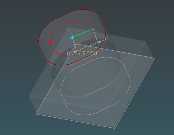
Operation Axis Tool
The Operational axis tool (toolbar tooltip: Operational axis) lets you define a reference line (a direction and a point it passes through) for mirroring and revolving operations in sketches. Only the direction and position matter; the length of the drawn helper segment is visual only and has no effect on the results.
The axis reference line is visible only while Operational axis mode is active. If you switch to another sketch tool, the axis is hidden in the view but remains defined until you Clear axis or reload without it. Operational axes are saved in the sketch JSON when you save the project.
Features:
Two-point definition |
Click to set the start point, then click to set the end point of the axis line |
Real-time preview |
See the axis line while moving the mouse |
Visual length control (Tab) |
Use the distance input dialog (Tab key) to set the length of the drawn helper segment (purely visual/reference; the length has no effect on mirror or revolve results) |
Angle constraint |
Use the angle input dialog (Shift+Tab) to constrain the direction of the axis line |
Mirror operations |
Use the defined axis to mirror selected edges |
Revolve operations |
Use the defined axis to revolve selected edges or faces |
Selection-friendly mirror/revolve |
After the axis is defined, permanent + markers and sketch snap are hidden so you can select edges and faces without snap clutter |
How to Use:
Phase 1: Define the operation axis
- Select Operational axis from the toolbar.
Click to set the start point of the axis line on the sketch plane.
Move the mouse — a live preview of the axis line follows the cursor.
Click a second point (or use the input dialogs) to finalize the axis:
Tab: open distance dialog to set the length of the drawn axis helper segment (visual only — this length does not affect mirror or revolve operations).
Shift+Tab: open angle (degrees, CCW from +X) dialog to constrain direction.
Apply angle constraint first if using both, then length.
The axis is now defined. You remain in Operational axis mode (this keeps the Options panel available for the Mirror/Revolve controls). Permanent + node markers and sketch snap are suppressed until you clear the axis or leave the tool.
Phase 2: Use Mirror or Revolve (the controls shown in the Options panel)
Once the axis exists, the Options panel (under the Sketch operation heading) displays these controls (matching the UI):
Mirror button — Mirrors the currently selected sketch edges across the axis.
Revolve button (with adjacent numeric input, default 360.00, and ? help) — Revolves the selected edges or faces around the axis by the given angle (in degrees). 360° on a closed profile produces a full solid of revolution.
Clear axis button — Removes the current operational axis (required before you can define a new one). Restores permanent node markers and sketch snap.
How to Mirror:
With Operational axis mode active and an axis defined, select the edges you want to mirror (click them or use a selection box; snap guides and + markers stay hidden so selection is unobstructed).
In the Options panel, click the Mirror button.
Selected straight edges are duplicated and mirrored. Arc/circle edges are handled as pairs to preserve the geometry.
The mirrored elements are added to the current sketch (the original selection remains until you change it).
How to Revolve (create 3D):
With Operational axis mode active and an axis defined, select the edges or closed faces you want to revolve.
(Optional) Adjust the angle in the input field next to the Revolve button (default 360.00 for a full closed revolution).
Click the Revolve button.
EzyCad creates a 3D body by revolving the selected sketch geometry around the axis. When you select edges rather than a face, it does its best to convert the result into a solid (see Revolve solid conversion). The new shape is added to the document and you are switched out of sketch mode into Normal (inspection) mode.
If the operation fails you will see a message such as “Revolve failed, ensure edges or faces on one side of operation axis.”
Redefining the Axis:
While an operational axis exists, clicks in the viewport select edges or faces for Mirror/Revolve (Operational axis mode stays active so the Options panel buttons are available). Snap and + markers remain off during this phase.
To redefine the axis: click Clear axis in the options panel first (this removes the current axis and restores snap/markers), then click in the viewport to place the first point of the new axis, followed by the second point (as in Phase 1 above).
Using the Operation Axis (UI reference): The controls that appear in the Options panel once an axis is defined are:
Control |
Purpose |
|---|---|
Mirror button |
Mirrors selected edges across the operation axis (stays in 2D sketch). |
Revolve button + numeric field (e.g. 360.00) + ? |
Revolves selected edges or faces around the axis by the entered angle. Use ? next to the angle field for solid-conversion notes. |
Clear axis button |
Manually removes the current operation axis reference. |
The Revolve numeric field accepts any float angle (in degrees); 360 is the most common for closed solids.
Revolve solid conversion
Open CASCADE often returns a shell or separate faces when you revolve a closed loop of edges rather than selecting a face. EzyCad then does its best to convert that result into a solid (sewing faces when needed, then wrapping a closed shell with MakeSolid) so downstream tools such as chamfer, fillet, and booleans can work.
Selection |
Typical OCCT output |
After conversion |
|---|---|---|
Closed face |
Solid |
Unchanged (already a solid) |
Closed edges (360°) |
Shell or compound of faces |
Converted to solid when possible |
Open edge or partial angle |
Surface / open shape |
Left as-is (cannot close into a solid) |
Use View → Shape List → Shape info… on the new body to confirm the root type is Solid. If conversion fails, try selecting the enclosed face instead of individual edges, or check that the profile is closed, does not cross the axis, and uses a 360° angle.
Tips:
Prefer selecting a face when one is available; that path usually produces a solid directly.
When using edges, select the full closed boundary of the profile.
Partial revolutions (angle < 360°) intentionally remain open surfaces.
Important note on axis length: The two points you pick define a direction and a point the axis passes through. The length of the drawn segment between those points is purely visual (it determines how long the reference line appears in the sketch for your convenience). It has no effect on the results of Mirror or Revolve. The operations always treat the axis as an infinite line in the computed direction.
Shortcuts:
Tab |
Open distance input dialog to set the length of the drawn axis helper segment (visual only; length has no functional effect on mirror/revolve) |
Shift+Tab |
Open angle input dialog to constrain the direction of the axis (after first point is set) |
Escape |
Cancel the current axis definition |
Angle Constraint:
After setting the first point, press Shift+Tab to open the angle input dialog
Enter the desired angle in degrees (0 deg = horizontal right, 90 deg = vertical up, counterclockwise)
Once the angle is entered, the axis line is constrained to that direction from the start point
You can still move the mouse to adjust the length of the drawn helper segment while maintaining the direction, or use Tab to set an exact visual length (note: the length of the operation axis segment has no effect on mirror or revolve results — only the direction and a point on the line matter)
The distance input (Tab) can still be used in combination with the angle constraint for the visual helper
Order when using both: When requiring both an angle and a length (for the helper), apply the angle constraint first (Shift+Tab), then the length (Tab).
Note: When an angle constraint is active, snapping to nodes is disabled to maintain the angle precision
Tips:
The operational axis is a reference line (direction + any point it passes through). Its drawn length is visual only and has no effect on mirror or revolve results.
The axis line is drawn only while Operational axis mode is active; other sketch tools hide it from the view without clearing the stored axis.
Select edges or faces (while Operational axis mode is active) before using the Mirror or Revolve buttons in the options panel
To redefine the axis, first use Clear axis, then place the new axis points (snap works again during placement)
Use snap points for precise axis placement relative to existing geometry (Phase 1 only)
Constraining the angle when placing the axis is useful for precise directional reference lines
You can make the drawn axis segment long or short via Tab purely for visibility/clarity — it does not change the behavior of the operations
Dimension Tool

Edge dimension tool creates/removes length dimensions between two sketch nodes.
Features:
Node-pair dimensions |
Dimensions are defined by two sketch nodes |
Fast edge workflow |
Click a straight edge to toggle a dimension between its two endpoint nodes |
Two-node workflow |
Click one node, then a second node, to toggle a dimension between them; after the first node, a preview line follows the cursor (same idea as the line-edge rubber band), so two-node mode is visually distinct from a single edge click |
Selectable/deletable |
Dimension objects can be selected in sketch mode and deleted (for example with Shift+D, Delete, or Backspace) |
Helpful for verification |
Quickly verify that your sketch has the correct dimensions |
Shortcuts:
D |
Activate dimension tool |
Shift+D, Delete, or Backspace |
Delete selected dimension (or other selection) |
How to Use:
- Press D or select the Edge Dimensions tool from the toolbar
Use either input style:
Edge click: Click a straight edge to toggle the dimension between its endpoints
Node pair: Click node A, then click node B to toggle the dimension between A and B
Click the same edge (or same node pair) again to remove that dimension
To delete directly, select the dimension object and press Shift+D, Delete, or Backspace
When to Use:
Design verification |
Check that your sketch dimensions match your design requirements |
Quality control |
Verify measurements before extruding or performing operations |
Learning and debugging |
Understand how your sketch geometry is sized |
Documentation |
Take screenshots with dimensions visible for reference |
Selective display |
Show dimensions only for the node pairs you care about |
Tips:
Dimensions display the distance between the two referenced nodes
Node hover/pick uses normal sketch snap distance rules
This tool is particularly useful when working with precise measurements
Use in combination with the distance input feature (Tab key) when creating edges
Dimensions are for display only and do not constrain the geometry
Toggle dimensions on only the elements you need to reduce visual clutter
Technical Details:
Dimension source |
Calculated from the two referenced nodes |
Unit system |
File -> Project units (Inches or Millimeters); dims and length entry follow it |
Auto-update |
Dimensions update automatically when geometry is modified |
View-only |
Does not affect the underlying geometry |
Add Node Tool

The Add node tool (toolbar: Add node) adds sketch vertices. What happens on each placement depends on whether you start from an existing node:
First click snaps to an existing node — The tool acts like Line edge for the next step: a rubber-band preview runs from that anchor, and you can enter length and/or angle (Tab / Shift+Tab, same order as line edge) before you place the second point. No new line edge is added to the sketch; only the new node is created at the end of that placement.
First click does not snap to an existing node — The new node is placed at the click on the sketch plane (usual snap rules still apply, e.g. mid-point snap onto a straight edge to split it).
In both cases, Add node never leaves a permanent edge between two clicks the way Line edge does.
What else it does
Mid-point snap / split |
If a click lands near a straight (non-arc) edge (not at its endpoints), the pick snaps onto the segment and that edge is replaced by two meeting at the new vertex. Arc edges are not split this way. |
No stored edge from anchor |
After a two-step placement from an anchor, no sketch edge is created between anchor and new node (unlike Line edge). |
Angle constraint |
With an angle constraint active during rubber-band placement, the next click places the new node along that ray from the anchor; snapping may be relaxed to stay on that direction (similar to the line tool). |
Permanent “+” markers
Each sketch includes a built-in Origin (see Sketch origin) — shown as a permanent + inside a circle on the active sketch when enabled in Sketch properties.
Nodes you place with Add node are treated as user-placed points. When the sketch is visible, eligible points can show a red + marker in the 3D view so you can see and pick them; you can delete user-placed markers from the selection. Geometry that exists only as automatic edge midpoints for snapping is separate (those nodes are not shown the same way; controlled by the Add midpoints to new linear edges setting in Settings > Sketch, default off).
How to use
Enter sketch mode and select Add node
on the toolbar.Direct node: Click where you are not snapping to an existing vertex (empty sketch area, or near a straight edge for mid-point snap, etc.). The node is created at the snapped position; mid-point snap on a straight edge splits that edge.
From an existing node (line-edge–like step): Click an existing vertex first so the first click snaps to it. A rubber-band preview runs from that anchor—use Tab / Shift+Tab for length/angle if you want—then click (or confirm) to place the second point. Only a new node is committed; no new edge is stored.
Repeat as needed for more nodes.
Shortcuts
Tab |
Distance input for rubber-band placement (when an anchor is active). |
Shift+Tab |
Angle input (degrees) for rubber-band placement. |
Escape |
Cancel the current placement or rubber-band step. |
Right-click |
Drop an incomplete rubber-band preview if you started from an anchor and have not placed the second point yet. |
Tips
Prefer Add node when you need extra vertices or edge splits without a new visible segment between the two clicks.
Use Line edge or Multi-line when you want a new edge between two locations.
Add node vs. Line edge
Add node |
Rubber band is for placement only; does not add a permanent edge between the two clicks. |
Line edge |
Two clicks (or numeric input) create a new line edge in the sketch. |
Create Sketch from Planar Face Tool

The create sketch from planar face tool allows you to extract the boundary of a planar face from an existing 3D shape and create a new 2D sketch from it. This is useful for reverse engineering, modifying existing shapes, or creating new features based on existing geometry.
Features:
Face selection |
Click directly on a planar face from an existing 3D shape |
Automatic boundary extraction |
Extracts the outer wire (boundary) of the selected face |
New sketch creation |
Creates a new sketch with the face boundary as the initial geometry |
Planar face requirement |
Only works with planar (flat) faces - curved or complex surfaces are not supported |
Error handling |
Displays an error message if a non-planar face is selected |
How to Use:
Activate Tool:
Click the Create Sketch from Planar Face tool from the toolbarSelect Face: Click on a planar face from an existing 3D shape
The face must be planar (flat) - curved surfaces like cylinders, spheres, or complex surfaces will show an error
The system will automatically extract the outer boundary of the face
Sketch Created: A new sketch is automatically created with:
The face boundary as the initial wire
The sketch plane aligned with the face plane
A permanent Origin marker (cyan + inside a circle) at the center of the face boundary’s bounding box (a fixed reference on the sketch plane)
The sketch name set to “Sketch from face”
Edit Sketch: You can now edit the sketch using standard sketch tools (add edges, modify geometry, etc.)
Requirements:
Planar face only: The selected face must be flat (planar). Common planar faces include:
Flat surfaces on boxes or rectangular shapes
Flat faces on imported STEP/IGES models
Top or bottom faces of extruded shapes
Any face that lies in a single plane
Error Handling:
If you select a non-planar face, you will see an error message: “Error: Selected face is not planar. Please select a planar face.”
The operation will be cancelled and no sketch will be created
Simply select a different face that is planar
Shortcuts:
Escape: Cancel the operation (if activated but not yet completed)
Tips:
Use this tool to extract profiles from existing 3D models for modification or reference
The created sketch can be edited, modified, and then extruded to create new features
Useful for reverse engineering or working with imported CAD models
The sketch plane will be automatically aligned with the face plane
After creating the sketch, you can add additional geometry or modify the extracted boundary
The original shape remains unchanged - this tool only creates a new sketch based on the face boundary
Common Use Cases:
Reverse engineering |
Extract profiles from imported 3D models |
Feature modification |
Create a sketch from an existing face, modify it, and extrude to create a new feature |
Reference geometry |
Use existing face boundaries as reference for new sketches |
Model editing |
Extract a face boundary, modify it, and use it in boolean operations |
Workflow efficiency |
Quickly create sketches from existing geometry instead of manually recreating profiles |
Technical Details:
Boundary extraction |
Uses |
Sketch plane |
Determined from the face’s underlying surface geometry |
Supported faces |
Only |
Sketch list |
Created sketch is added and can be managed like any other sketch |
Image underlay
Import a reference image (PNG, JPEG, or BMP) behind a sketch for tracing or alignment. Open Sketch properties from the Sketch List ([P] on the sketch row) or use the underlay controls there after import.
Sketch List shortcuts
Control |
Action |
|---|---|
Underlay checkbox |
Show or hide the underlay for that sketch (only when an image is loaded) |
|
Open Sketch properties for import, calibration, and transform |
Sketch properties — Image underlay
Control |
Action |
|---|---|
Import image… |
Load PNG/JPEG/BMP into the current sketch |
Remove underlay |
Clear the image from the sketch |
White paper -> transparent |
Treat bright pixels as clear (typical for scanned line drawings; turn off for photos) |
Tint visible lines / Line color |
Recolor non-transparent pixels after the white key (default amber/gold for contrast on dark backgrounds) |
Opacity |
Overall underlay transparency (0–1) |
Calibrate from sketch edges (sketch must be current in the Sketch List):
Button |
Action |
|---|---|
Set X from edge… |
Two clicks along bitmap width (+U), then enter the real drawing distance (same units as sketch dimensions) |
Set Y from edge… |
Two clicks along bitmap height (+V), then enter the drawing distance for Y |
After edge calibration, bitmap axes may be non-orthogonal (shear). In that case the Transform section switches to a 6-DOF affine editor instead of the sliders:
Base X / Base Y — location of the bitmap corner (0,0) in sketch-plane coordinates.
U X / U Y and V X / V Y — the two edge vectors defining the image parallelogram (+U is width direction, +V height). Their lengths and the angle between them are shown below the inputs for reference.
When shear is present, a checkbox “Show raw shear distortion in image” appears. Turn it on to make calibration mistakes (such as an incorrect Y-axis pick) visible directly as skew and distortion in the raster image pixels themselves. This complements the cyan bounds, which always show the exact current parallelogram. The default (off) uses special resampling so the source image content looks clean relative to your U/V axes.
Two additional checkboxes (Reverse image U / Reverse image V) appear in raw mode. These flip the source raster data so that raster (0,0) lands at the corner of the parallelogram you expect. They exist because exact texture UV ordering on a sheared OCCT face created from a wire can vary.
Auto-orthogonal after calibration: once you have successfully set both X and Y (via the edge tools), the system automatically applies the equivalent of “Make orthogonal (keep lengths + U direction)”. This forces V perpendicular to U while preserving the two calibrated lengths, so the friendly sliders usually become available again. You can still re-introduce shear manually in the 6-DOF editor or via the button.
Transform (orthogonal underlay): sliders and Rotation value adjust center, half extents, and rotation on the sketch plane; changes apply in real time and support undo. When shear is present the sliders are replaced by the raw basis editor above so the calibrated fit is not lost.
Known limitations with image underlays (as of the current version):
“Set X from edge…” and “Set Y from edge…” measure along the current basis at the time of the pick. If the two features you pick are not perfectly perpendicular in the source image (or your clicks are slightly off), the resulting U and V will not be orthogonal. This is supported (full affine), but it disables the simple sliders and can make the image content appear skewed until you use the raw editor or the Make orthogonal button.
The “Define underlay datum…” tool (which forced a clean perpendicular V) has been removed.
The entire source image (including margins, title block, etc.) is always mapped to the current parallelogram. If you only care about part of the image you may need to pre-crop the file.
In raw shear mode the visible textured region follows the exact parallelogram (cyan frame), but achieving pixel-precise “raster (0,0) at this exact corner” can require the Reverse U/V flips because of how OCCT parametrizes faces created from a general wire.
The two renderer paths (default “preserve” vs. raw) produce visibly different results for the same affine. The preserve path counteracts texture shear for a cleaner look; raw lets the affine act directly on the pixels (deliberately for calibration debugging).
The cyan frame is always the exact geometric bounds of the full mapped source image. It is not a crop rectangle.
Changes apply live and support undo. A Make orthogonal (keep lengths + U direction) button (and the automatic version after both axes are set) projects V to be perpendicular to U (preserving lengths and winding) and returns you to the friendly Center / Half / Rotation sliders.
Default underlay highlight tint for new imports: Settings -> Sketch -> Underlay highlight color (see usage-settings.md).
A thin cyan frame (parallelogram when the underlay has been calibrated with shear) is always rendered around the exact bounds of each visible image underlay. This makes the placement and extent clear for new imports and in cases where most of the bitmap content keys to transparent.